Control Panel construction
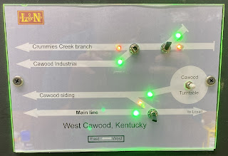
I have developed a method to create nice control panels for my layout. The turnouts on the layout are controlled by DPDT switches on a control panel. Bicolor LEDs indicate the route. Below is a picture of one of them.
Below is how I make them.
Electrical Components
DPDT on-on mini-toggle switch (need 1 per turnout to be controlled)
3 mm Red-Green LEDs, EdgeLEC from Amazon. These come with the resistors. (need 2 per turnout)
22 gauge wire in various colors. I use solid core wire, but stranded will also work.
Other Materials are available at most home improvement stores, such as Home Depot.
0.097” thick Plexiglass
A sturdy razor knife or Plexiglass knife
1” sheet rock screws to attach the panel to the fascia
Soldering iron and solder
Miscellaneous hand tools; pliers, small screw driver, etc..
The panels are drawn in Apache's Open Office Draw. The panels have a grey background with white lines and text, which looks good next to the black fascia. Here is a picture of a recent panel I drew and printed.
I printed the panel drawing on photo paper and glued the drawing to black construction paper and used an X-acto blade to trim the edges. This gives the panel drawing some stiffness to avoid curling and also helps to block light from shining through.
Cut a matching piece of 0.097” thick (probably considered 0.100 “ or 2.5 mm) Plexiglass. I find using a razor blade in a heavy holder works better to score the Plexiglass than a linoleum knife.
Carefully lined up the Plexiglass and the drawing and measure to the vertical center of the drawing and 3/8” in and marked with a red marker. This is where the mounting screws will go. Remove the drawing and drill 9/64” holes through the Plexiglass for each mounting screws. I find that 1 screw on each side is adequate to secure the Plexiglass to the fascia. Then put the drawing back under the Plexiglass, align the mounting holes, and with a fine tipped pencil, outline the holes onto the drawing. I then used a 3.5 mm leather hole punch to cut the holes in the drawing.
Moving onto the holes for the electrical switches, I used an awl to start the hole in the Plexiglass over the “X”s on the control panel drawing, which is where the switches go. You have to be careful as the Plexiglass will crack if you drive the awl too deep. Then I removed the control panel drawing and used a 19/64” drill bit to drill the holes in the Plexiglass. (The larger drill bit is a challenge to center properly and tends to “drift”. Perhaps drilling a smaller pilot hole first would help.) I then realigned the Plexiglass with the drawing and with a fine tipped pencil I outlined each of the holes onto the drawing. I then used a 5 mm leather hole punch to cut the holes in the drawing.
The bi-color leds have 3 legs and thus don't fit into panel mounts. So we will superglue the LEDs to the back of the control panel drawing. The LEDs are nominal 3 mm which is 0.120”, but they measure as 0.119” in diameter and 0.159” tall above the “rim” at the LED's base. The control panel drawing is only 0.021” thick, so I'll have to drill holes in the Plexiglass for the LEDs to insert into. Carefully drill 1/8” (0.125”) holes in the Plexiglass for the LEDs and to use a 2.5 mm hold punch to cut the drawing and then superglue the LED to the back of the drawing.Drilling the holes in the Plexiglass for the LEDs. and punching the holes in the drawing worked pretty well, except for one thing. When using the awl, it was difficult to hit the center of the red/green dots on the drawing. As a result some of the holes in the Plexiglass are off center from the colored dots on the drawing. Not by much, just enough to leave a slim green or red line around the LED's hole. In the future drawings, I need to make these dots smaller. Also because of the above, some of the holes don't quite match up between the Plexiglass and drawing. Putting screws in the mounting holes while marking the holes for the electrical components may help.
I use discrete resistors (430 + 470 ohm in series, ¼ watt) for each LED on its cathode leg. I do note that the green LEDs are much brighter than the red. The resistors came with the LEDs as a package. Perhaps in the future I will use larger resistors to dim the LEDs a bit.
And here is a look at the finished product. Here two of my control panels can be seen on my layout.
That's all for now. Happy model railroading.


